
THERMAL FOAM GASKET (TFG)
Features
- Using a graphite sheet has excellent horizontal thermal conductivity, it drops the heat of heat source by spreading the heat quickly from the heat source.
- Graphite-particle does not occur by coating all surfaces of graphite with a thin film.
- A wide utilization without thickness of constraint that is the disadvantage of silicone thermal pad. - Example( in 10mm, 20mm , 30mm or more thickness, thermal performance shows)
- The excellent compression resilience by using the heat polyurethane sponge.
- No problem with bending of the circuit board due to the excellent elastic polyurethane sponge core.
- Easy to manufacture gaskets of various sizes.
- Because it does not need a special mold, it is possible to produce goods of any size you want promptly.
- According to the needs of users, thermal conductivity and compressive strength can be adjusted simply.
- Hold a number of patents
- We can guarantee the quality and patents of Graphite sheet used in products by contracting with E-GrafTech Inc.
Concept and Purpose
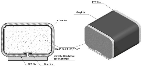
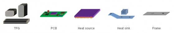
TFG deliver the heat of heat source to the heat sink or metal frame. It uses to drop the temperature of circuits by dispersing the heat of heat source widely.
» Overall height of 10 to 15% is appropriate for pressure conditions of TFG.
» Application Equipments:Electronic devices such as Display Module (LCD,LED,OLED TV, MONITOR)、Computer、MOBILE)
Way to Use
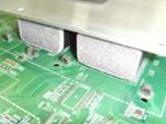
TFG is a new concept of the gasket. As below pictures, it can be effectively thermal conductivity even located in several different ways such as the side or the top side, or a gap between heat sieve and heating element.
Heat sieve : Heat sink, Metallic BACK COVER, metal frame
Heating element : IC devices, such as circuit boards
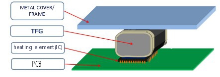
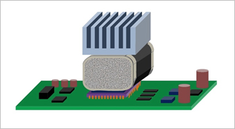
This is the most common method.
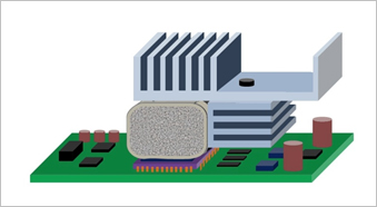
Heat sink attached to the side, you can increase the heat.
If there is no vertical space, Heat sink can be attached to the side.
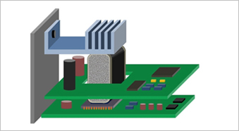
TFG is available to heat by grounding heat source between PCB and PCB. (Heat pipe’s role)
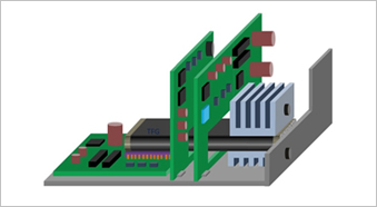
TFG can be heat through the PCB.
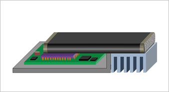
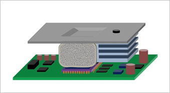
TFG as well as the top and sides can be applied to the bottom.
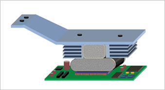
By applying two TFG can effectively maximize the heat.
■ Test of gasket state There is no limit of the thickness by using high flat thermal conductivity of graphite.
 |
Model : ASTM C518
Sample size : 28mm X 30mm X 10mm(T);
Graphite 400㎛; 20% pressure
Test method
1.It is a method to test thermal conductivity to measure the value of passing the heat by applying heat to top and bottom side.
2.It calls “Plate method“.
3.It is possible to test thermal conductivity of top and bottom of sheets or products.
4.Set the temperature of top & bottom side.
5.Put the sample.
6.In addition, measure thermal conductivity after pressing the press of top and bottom side.
 |
Model : HC110 (EKO Instruments사)
Thermal conductivity test : 0.1 ~ 10 W/mK
Test temperature range : 0 ~ 110℃
Accuracy : Within 5%
Thermal control : ±0.001℃
Test sample size : 51 ~ 63 mm(Dia.)
■ comparison test method(ESQ-517-22)
| » TFG sample, size 28(W) x 32(L) x 10.5(T) » Compared sample(silicone thermal pad), size(28(W) x 32(L) x 10.5T) » Heating plate heats up to 150 ℃. » After attaching TFG samples, you measures the time that thermal sensor will be from 40 ℃ to 80 ℃. » Thermal conductivity comparison test results (VS silicone thermal pad) see the following table. Test method 1. A test method is measuring the time of temperature change of bottom and top plate. 2. Set the temperature of bottom to 150℃. 3. Put the product on bottom plate, and put it on the top plate then, put weight of 1KG on the top. 4. Measure time of the temperature gauge of the top from 40℃ to 80℃. 5. It can make relative comparison. 6. It is a test method to measure the time of horizontal or vertical conduction. |
 |
Thermal conductivity comparison test results
| Thermal pad | Division | Average time to reach |
|---|---|---|
| Silicone thermal pad | 2.3 W/mK | 18’ 36” |
| 3 W/mK | 9’ 29” | |
| 5 W/mK | 7’ 35” | |
| TFG | - | 3’ 11” |
※ The advantage of TFG compared to the Silicone thermal pad » Silicone thermal pad used for a long time causes a siloxane but, TFG doesn’t cause it.
» Silicone thermal pad that is not good compression resilience has poor adhesion. However, TFG can be a thermal effect continuously with excellent adhesion.
» Silicone thermal pad can be hardened if used for a long time. It is a principal cause of failure such as bending of the circuit board due to continued pressure. But, TFG has high elasticity does not put pressure on a circuit board.
» The more silicone thermal pad is thicker, the more heat transfer capability is reduced. However, TFG is excellent horizontal thermal conductivity (>400W/km) of graphite can be a thermal effect regardless of any thickness.
Application example
Test of comparing temperatures when TFG attached on TV (“before” and “after”)
<Test condition>
› samples : TFG, Side Slit TFG
› TV : company’s LED Smart TV
› size : 32 X 28 X 12(T) [mm]
› condition : Measuring IC temperatures after turning on TV during 90 minutes (back-cover closed)
< Test result >
| Sample | IC Temp. [℃] | Indoor Humidity [%] | Indoor Temp [℃] | Remark |
|---|---|---|---|---|
| General TFG | 46.4 | 43 | 20.4 | Graphite 2 types |
| Insulated graphite type TFG | 50.9 | 46 | 20.9 | Graphite 2 types (PET insulation of graphite edge) |